In Part 3 of this series, we examined HOSP-EVAC-001, evaluating how door widths and host space definitions determine clear width compliance.
Getting through the doorway, however, is only the initial step of an evacuation sequence. Once a patient bed, assisted wheelchair user, or rapid-response crash team passes through a door, three practical spatial engineering questions immediately arise:
- Corridor Clear Width (
HOSP-EVAC-002): Is the circulation corridor wide enough along its entire physical run—including around sharp corners, recesses, and structural column intrusions—to satisfy the 2.00m bed-passing benchmark in NHS Health Building Note HBN 00-04? - Egress Travel Distance (
HOSP-EVAC-003): How far must an occupant actually walk—through doorways and navigating around solid partition barriers—to reach the nearest protected fire stair or ground-floor final exit under NHS HTM 05-02 Firecode (≤ 30.0m two-way travel, ≤ 15.0m single-direction dead-end)? - Evacuation Stair Geometry (
HOSP-EVAC-004): When they reach the stair core, does the stair flight provide at least 1.20m of unobstructed clear width and a pitch angle within 33.0° per HBN 00-04 and BS 8300-2:2018?
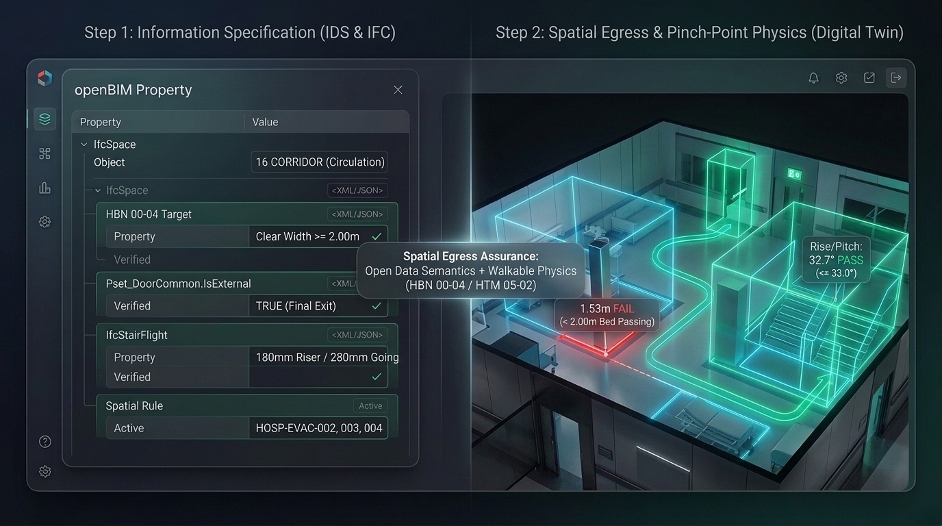
"Open data standards (IFC and IDS) and 3D spatial geometry are not competing concepts. They are two complementary halves of the exact same digital assurance pipeline."
Why We Need Both: IDS Identifies the Ingredients, Geometry Measures the Space
Under buildingSMART's Information Delivery Specification (IDS), information managers can verify that model elements are correctly classified and populated with contractual metadata:
- Rooms and circulation zones are exported as
IfcSpacewith standardized naming or classifications (CORRIDOR,OR,ICU ROOM). - Doors possess
Pset_DoorCommon.IsExternalso software can distinguish an external ground-floor discharge door from an internal consulting room door. - Stairs are typed as
IfcStairorIfcStairFlightand carry riser and going design parameters.
Without that metadata, any automated checking engine is flying blind. You cannot check corridor clearance if you cannot programmatically isolate corridors; you cannot calculate evacuation routes if exit doors lack external attributes.
However, once IDS confirms that those semantic ingredients exist, a physical measurement must still be executed across the 3D space:
🔍 Step 1: Metadata & Semantics (IFC & IDS)
- Classify Spaces: Identifies corridors, operating rooms, and wards.
- Identify Targets: Flags protected stair shafts and external exit doors.
- Identify Obstacles: Parses physical walls, columns, and railings.
- Limitation: Static properties cannot measure localized column restrictions or navigate around walls.
📐 Step 2: 3D Geometric Verification (bim-checker)
- HOSP-EVAC-002: Extracts true 3D boundary and narrowest pinch-point measurement.
- HOSP-EVAC-003: Traces walkable floor paths through doors and around solid partitions.
- HOSP-EVAC-004: Verifies orientation-independent flight clear width and pitch.
- Outcome: Honest, defensible life-safety validation without false alarms.
Consider what happens if an information team attempts to verify corridor widths, evacuation travel distances, or stair clearances using static text properties alone:
- No one manually types in a localized pinch point: An architect may schedule a corridor with a nominal design width of 2.10m. Nobody manually locates an en route column protrusion or duct riser encroachment and types
PinchPointWidth = 1.78minto an IFC property set so an isolated property checker can flag it. - Travel distance is a spatial relationship, not an isolated room attribute: The walking distance from Operating Theatre 154 to the nearest fire exit depends on where the door is placed, how corridor walls are laid out, and where the protected stair enclosure sits on that storey. If a partition moves during design development, any hardcoded "travel distance" property immediately becomes obsolete.
- Bounding boxes are not measurements: When basic checking scripts read Axis-Aligned Bounding Boxes (
BBoxHigh - BBoxLow) to avoid true 3D geometry, rotated stair flights, L-shaped circulation wings, and partition layouts produce wildly inaccurate figures—either masking severe defects or drowning coordinators in false alarms.
In modern BIM validation software like bim-checker, we pair openBIM metadata directly with live 3D geometric calculation. Below is what HOSP-EVAC-002, HOSP-EVAC-003, and HOSP-EVAC-004 uncover across the open Autodesk Hospital Sample Project (WRSH_Architectural.ifc).
1. HOSP-EVAC-002: Measuring True Corridor Widths and Pinch Points
In healthcare facility design, NHS HBN 00-04 mandates a minimum unobstructed width of 2.00m along patient circulation corridors to allow two hospital beds, or a bed and a resuscitation trolley, to pass without obstruction.
Why Bounding Boxes Fail on L-Shaped Corridors
When our BIM model inspection tool queries WRSH_Architectural.ifc for designated corridor spaces, it analyzes two primary spaces on Level 2:
112 CORRIDOR(0x20000000ec4): A straight corridor segment with an area of 14.07 m².16 CORRIDOR(0x20000001577on Level 2): An L-shaped circulation corridor wrapping around a clinical wing, with an IFCGrossFloorAreaof 59.34 m².
If an automated tool simply takes the Axis-Aligned Bounding Box (min(Δx, Δy)) of 16 CORRIDOR, the bounding box spans the entire L-shaped envelope:
Axis-Aligned BBox Calculation: Δx = 19.48m, Δy = 11.08m → min(Δx, Δy) = 11.08m
Reporting that a hospital corridor is 11.08m wide is completely unhelpful—it measures the outer extent of the L-bend rather than the usable width of the circulation route.
Measuring the Real Passage and Column Pinch Points
Instead of trusting a bounding box or expecting a designer to manually input a clear width property, bim-checker extracts the actual 3D space boundary of the corridor, detects physical structural columns or service risers encroaching into the walking path, and analyzes the continuous spine between doorways to measure the narrowest physical pinch point.
| Corridor Space | Element ID | Bounding Box | True 3D Geometry | Measured Width | HBN 00-04 Target | Audit Result |
|---|---|---|---|---|---|---|
| 112 CORRIDOR | 0x20000000ec4 |
1.78m × 7.92m | Straight 3D Space Boundary | 1.78m | ≥ 2.00m | FAIL (−220mm) |
| 16 CORRIDOR (Unobstructed Wall-to-Wall) |
0x20000001577 |
19.48m × 11.08m | L-shaped 3D Space Boundary | 2.17m | ≥ 2.00m | PASS (Resolves BBox) |
| 16 CORRIDOR (At Column Encroachment) |
0x20000001577+ 0x20000001833 |
Column 475×475mm intrusion | Boundary + Structural Column | 1.53m – 1.68m | ≥ 2.00m | FAIL (Column Pinch) |
In the 3D viewer, bim-checker renders both the true floor footprint (shaded emerald for pass or red for fail) and a high-contrast pinch-point dimension line directly across the narrowest restriction—so the BIM engineer can visually inspect and verify where the 1.78m or 1.53m bottleneck occurs without hunting through 2D drawings.
2. HOSP-EVAC-003: Walkable Egress Routing vs. Straight-Line Approximations
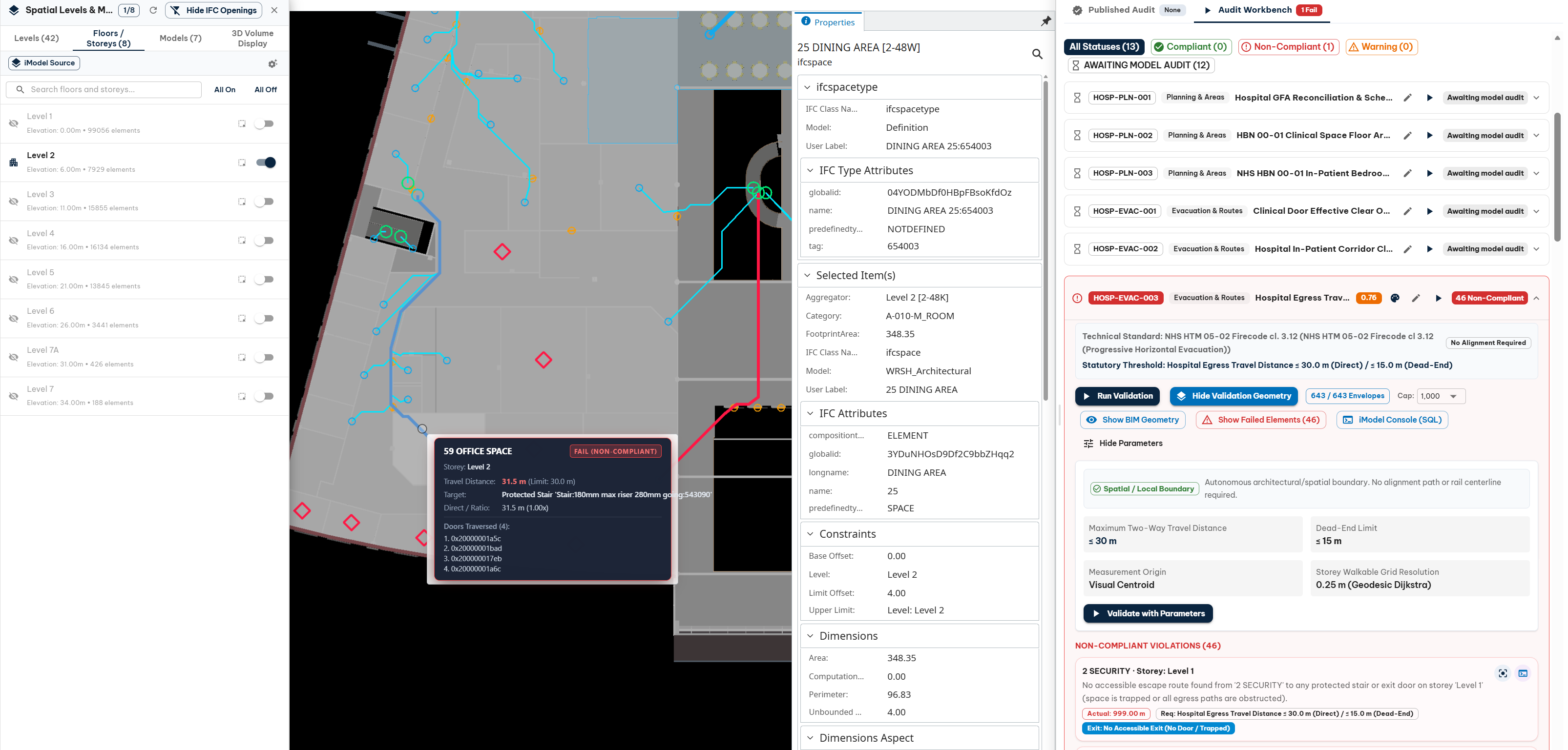
Under NHS HTM 05-02 Firecode (cl. 3.12), healthcare premises employ Progressive Horizontal Evacuation (PHE), where occupants and patients are moved into an adjoining fire compartment or protected stair enclosure within ≤ 30.0m (or ≤ 15.0m in a single-direction dead-end).
Why can't you calculate travel distance using a simple coordinate distance formula between a room and a stair? Because coordinate math cuts straight through solid walls and ignores ground-floor exit doors.
When we compared a traditional Manhattan approximation ($|\Delta x| + |\Delta y| + \frac{1}{2}\text{RoomDiagonal}$ to the nearest stair) against bim-checker's walkable route analysis across all 193 rooms in WRSH_Architectural.ifc, the audit revealed two equally vital realities: simple coordinate math creates false alarms on the ground floor, while missing dangerous long walks on upper clinical floors.
Side A: Eliminating False Positives on the Ground Floor
Under the naive Manhattan-to-stair approximation, 50 of the 193 spaces appeared to fail the 30.0m limit. Many of those were ground-floor rooms near the main entrance—such as 2 SECURITY (0x20000000e09) and 1 TRIAGE REGISTRATION (0x20000000e08)—because the nearest internal stair shaft (Stair:534855) was over 34m away.
In reality, someone in the Ground Floor Security office does not walk 40m deeper into the hospital to climb an internal staircase during an evacuation—they exit directly through the front entrance doors (Curtain_Wall_Automatic_Sliding_Door_1832:Store Front Double Door:950392, where Pset_DoorCommon.IsExternal = TRUE).
| Ground Floor Space (Level 1) | Element ID | Naive Manhattan to Stair | Walkable Route (HOSP-EVAC-003) | Escape Target Used | Real Status |
|---|---|---|---|---|---|
| 2 SECURITY | 0x20000000e09 |
40.6m (False Fail) | 7.5m (9.9m corner) | External Exit Door 950392 (IsExternal = true) |
PASS (≤ 30m) |
| 1 TRIAGE REGISTRATION | 0x20000000e08 |
34.5m (False Fail) | 16.2m | Protected Stair 534855 |
PASS (≤ 30m) |
| 7 GIFT SHOP | 0x20000000e32 |
39.1m (False Fail) | 18.5m (24.1m corner) | Protected Stair 642711 |
PASS (≤ 30m) |
| 106 RECEPTION | 0x20000000ebe |
48.6m (False Fail) | 21.9m (27.1m corner) | External Exit Door 950392 (IsExternal = true) |
PASS (≤ 30m) |
Here, IDS metadata (IsExternal = TRUE) and 3D walkable routing work together to eliminate 28 false-positive alarms, building trust with design leads by preventing time wasted chasing phantom non-compliances.
Side B: Catching Real Wall Detours in the Operating Theatres
Now look at the opposite effect on Level 2 (Z = 6.0m to 10.0m elevation, containing 91 of the hospital's 193 spaces), inside the surgical block (154 OR, 155 OR, 156 OR, 157 OR):
In a straight coordinate check, Operating Theatres 154 through 157 sit physically close to adjacent stair shafts (541718, 539339, 622923, and 641039)—their straight-line Manhattan distances are between 21.1m and 29.2m. A basic property formula marks all four operating theatres as PASS (≤ 30.0m).
Why is that dangerous? Because an operating theatre is enclosed by solid sterile partition walls with no direct opening into those adjacent stair shafts. You cannot walk through the back wall of an operating theatre into a stair core. Staff and patients must exit through designated doors into the sterile corridor spine (160 STERILE PREP), navigate around partition enclosures, and reach the accessible stair enclosure (Stair:534855).
| Surgical Space (Level 2) | Element ID | Straight Distance (Ignores Walls) | Walkable Path (Centroid) | Farthest Corner Walk | Reachable Stair | Real Status |
|---|---|---|---|---|---|---|
| 154 OR (Operating Theatre) | 0x200000016dc |
28.3m to `Stair:622923` (False Pass) | 40.4m | 42.8m | Stair:534855 |
EXCEPTION (+10.4m) |
| 155 OR (Operating Theatre) | 0x200000016dd |
21.1m to `Stair:541718` (False Pass) | 36.2m | 40.5m | Stair:534855 |
EXCEPTION (+6.2m) |
| 156 OR (Operating Theatre) | 0x200000016de |
25.4m to `Stair:539339` (False Pass) | 33.6m | 37.4m | Stair:534855 |
EXCEPTION (+3.6m) |
| 157 OR (Operating Theatre) | 0x200000016df |
29.2m to `Stair:641039` (False Pass) | 35.9m | 39.7m | Stair:534855 |
EXCEPTION (+5.9m) |
| 148 ICU ROOM | 0x200000016be |
47.5m to `Stair:641039` | 30.6m | 35.0m | Stair:291848 |
EXCEPTION (+0.6m) |
Across the 193-room hospital model, HOSP-EVAC-003 identifies 22 rooms whose centroid walking route exceeds 30.0m, plus 15 large multi-bed ward spaces (37 total) where the room centroid is within 30.0m of a stair, but whose deepest bed bay reaches 32.1m.
🛡️ Topological Quality: Zero Connectivity BIM Checking in Circulation Networks
An escape path can only be calculated if spaces and doors form a continuous mathematical graph. During large-scale coordination, broken containment loops, unhosted doors, or boundary gap mismatches frequently create orphaned spaces. As an automated feature of modern BIM validation software, zero connectivity BIM checking traverses the spatial relationship graph to identify any clinical space, consultation room, or staff area that possesses zero valid connection to a circulation corridor or escape stair. Instead of letting orphaned rooms silently pass an isolated property check, zero connectivity BIM checking flags disconnected spaces before statutory submissions.
3. HOSP-EVAC-004: Measuring Escape Stair Widths and Pitch Without False Handrail Clashes
Once an evacuation route reaches a stair enclosure, HOSP-EVAC-004 evaluates the physical stair elements (32 IfcStair instances across 8 storeys in WRSH_Architectural.ifc) against NHS HBN 00-04 and BS 8300-2:2018 (cl. 7.3):
- Minimum Clear Flight Width: ≥ 1.20m
- Maximum Stair Pitch: ≤ 33.0° (derived from riser and going dimensions, e.g., 180mm max riser and 280mm going).
Measuring stairs reliably in an automated BIM model inspection tool requires solving three geometric hurdles:
- Orientation-Independent Width Measurement: Stair flights are routinely rotated relative to the project coordinate grid. Taking a world-aligned bounding box drastically inflates the apparent width of diagonal stairs.
bim-checkermeasures stair geometry along its true flight vector to extract real clear width and run length regardless of rotation. - Distinguishing Integral Handrails from External Obstructions: A compliant stair requires handrails (
IfcRailing), balustrades, and stringers. If a naive collision checker treats every railing as an encroaching obstacle, it subtracts the handrail projection from the flight width—falsely turning a fully compliant 1.30m stair (Stair:534855withRailing:534860) into an apparent failure.bim-checkerfilters integral stair hardware while continuing to catch structural column encroachments (IfcColumn). - Combining Semantic Riser/Going Data with Geometric Pitch: Where the authoring model includes riser and going specifications (e.g.
Stair:180mm max riser 280mm going:534855), the rule validates the design pitch: $\theta = \arctan\left(\frac{180\text{mm}}{280\text{mm}}\right) = \mathbf{32.7^\circ} \le 33.0^\circ \implies \mathbf{PASS}$ When riser/going parameters are absent, it calculates the geometric pitch from the 3D rise and run vectors.
♿ Automated Accessibility BIM Checks Across Public & Healthcare Assets
Statutory compliance under NHS HBN 00-04, Approved Document M (Volume 2), and BS 8300-2:2018 places strict dimensional obligations on vertical and horizontal access. Performing rigorous accessibility BIM checks requires verifying that flight clear widths (≥ 1.20m), pitch angles (≤ 33.0°), and corridor bed clearances (≥ 2.00m) are measured against true physical obstacles. Automating accessibility BIM checks eliminates subjective manual dimensioning and ensures that healthcare assets provide genuine, barrier-free access for assisted evacuation.
🏭 Beyond Healthcare: Egress Routing in Industrial BIM Validation
While this benchmark illustrates hospital circulation, the exact same spatial algorithms power industrial BIM validation. In high-bay logistics warehouses, battery gigafactories, and industrial process plants, circulation corridors are replaced by forklift transit aisles, overhead crane corridors, and process escape walkways. In industrial BIM validation, tracing true walking distances around racking structures, hazardous equipment zones, and conveyor lines without clipping through physical machinery is just as vital to statutory fire and life-safety sign-off.
Summary: Honest Engineering Assurance on the Digital Twin
| Rule Code | What IDS / Metadata Provides | What 3D Geometry Measures in bim-checker | Real Finding on WRSH_Architectural.ifc |
|---|---|---|---|
| HOSP-EVAC-002 Corridor Clear Width |
Identifies IfcSpace corridors and physical column obstacles. |
Evaluates true boundary and column encroachments to find narrowest pinch point. | Resolves 11.08m BBox to 2.17m; flags column restriction at 1.53m – 1.68m (< 2.00m). |
| HOSP-EVAC-003 Egress Travel Distance |
Identifies rooms, stairs, barriers, and IsExternal = TRUE exit doors. |
Traces actual walkable routes per storey through doors and around walls to valid exits. | Eliminates 28 false alarms; catches 4 Operating Theatres at 33.6m – 40.4m (> 30.0m). |
| HOSP-EVAC-004 Escape Stair Width & Pitch |
Identifies IfcStair elements and parses riser/going specifications. |
Measures flight width along true flight vector and validates 3D pitch. | Verifies Stair:534855 at 1.30m clear width (≥ 1.20m) and 32.7° pitch (≤ 33.0°). |
This is why accessing and measuring 3D spatial geometry is essential. We do not need to fabricate defects or abandon open standards: IDS ensures the model speaks a structured semantic language, and 3D geometric analysis measures the physical reality that no one should have to enter by hand.
🤝 Open to Engineering Peer Review: Inspect Our Methods First-Hand
At C&C Solutions, technical transparency and engineering integrity are our primary commitments. We believe BIM Engineers, Fire Engineers, and Principal Designers should never have to accept an unverified "black box" when certifying statutory compliance:
- Verify Live in the 3D Viewer: Every calculation in our BIM model inspection tool generates visible 3D validation geometry—corridor footprints, exact pinch-point lines, and walkable egress routes—so you can inspect every finding directly on the model at bim-check.itwin.app.
- Restricted Data Reality: Validation and proof are two distinct phases. While we showcase the spatial nuances of hospital design, real-world authoring often overlooks basic classifications, making automated model assurance essential.
The Future of Automated Model Checking Series Roadmap
- ✅ Part 1: Beyond the Checklist – Why Property Validation (IDS) Fails Real-World BIM Compliance
- ✅ Part 2: The Planned vs. Actual Dilemma – Reconciling Gross Floor Area Across Hierarchies
- ✅ Part 3: The 900mm Illusion – Evaluating Real Door Clearances and Spatial Column Clearances
- 📍 Part 4: Beyond the Property Tag – Measuring Real Corridor Pinch Points, Stair Flights, and Walkable Egress Routes (This Article)
- ⏳ Part 5: The Linear Leap – Why Vertical Building Rules Collapse on Linear Rail & Highway Infrastructure
- ⏳ Part 6: The Stepping Distance Dilemma – Validating the Platform-to-Train Interface (PTI) in 3D
- ⏳ Part 7: Airspace Along the Line – Overhead Footbridges, Dynamic Gauges, and Boundary Fencing
- ⏳ Part 8: Where Civil Meets Systems – High-Voltage Clearances (OCLZ/CCZ) and Track Integration
Join the Discussion
- How does your engineering team currently verify corridor pinch points and statutory escape travel distances across complex floorplates?
- Have you experienced instances where naive bounding boxes or straight-line travel formulas generated misleading compliance scores?
- If you are a BIM Manager, Fire Engineer, or Lead Designer interested in testing automated geometric checks on your proprietary models, contact our team—we would welcome the opportunity to review your requirements.
Acknowledgments: The hospital model referenced in this article is the open Autodesk Hospital Sample Project (WRSH). We express our sincere thanks to Autodesk for providing this multi-disciplinary dataset to the AEC engineering community.
#BIMValidationSoftware #ZeroConnectivityBIMChecking #AccessibilityBIMChecks #IndustrialBIMValidation #BIMModelInspectionTool #OpenBIM #IDS #DigitalTwins #BentleyiTwin #HealthcareEngineering #FireSafetyBIM